I have a few files of projects that Mr. Pete has made in videos and for which plans are available. One of these is the Bell Center Punch. It is fairly simple to make. It requires good concentricity between the hole through which the punch slides and the inside of the cone.
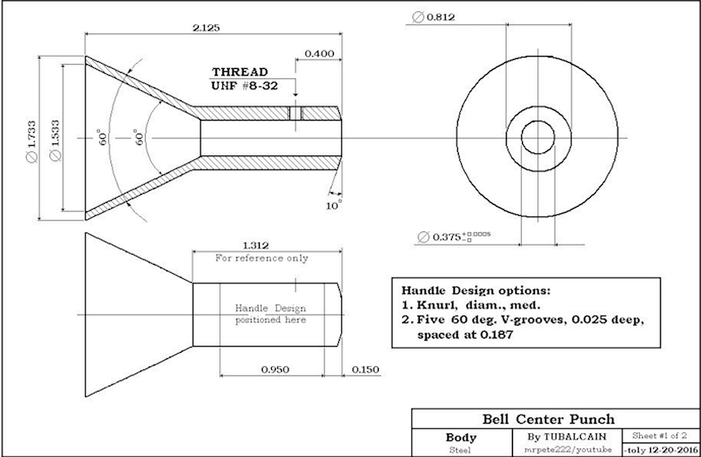
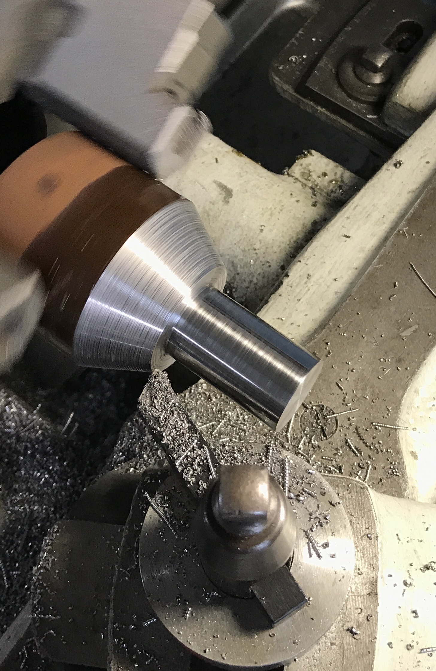
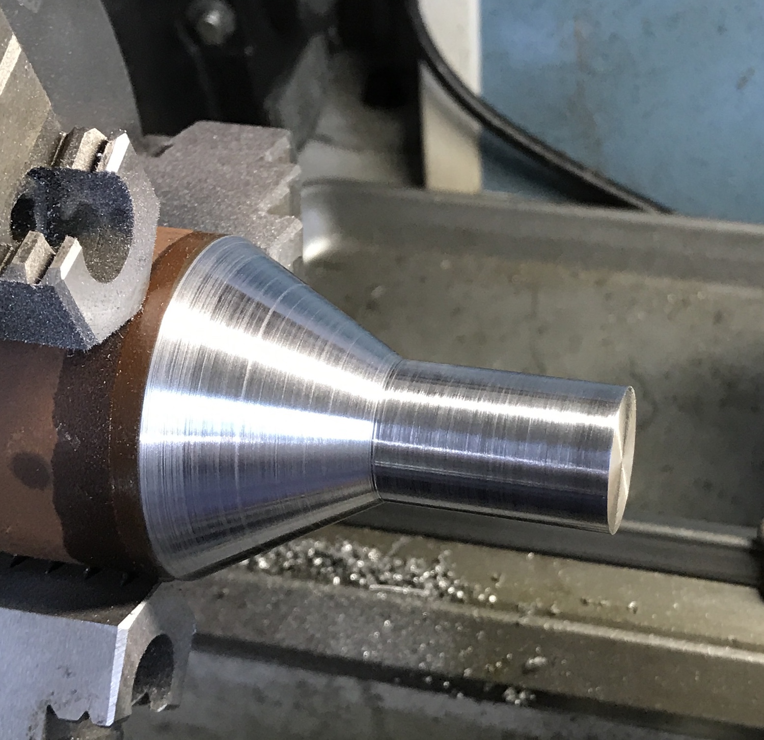
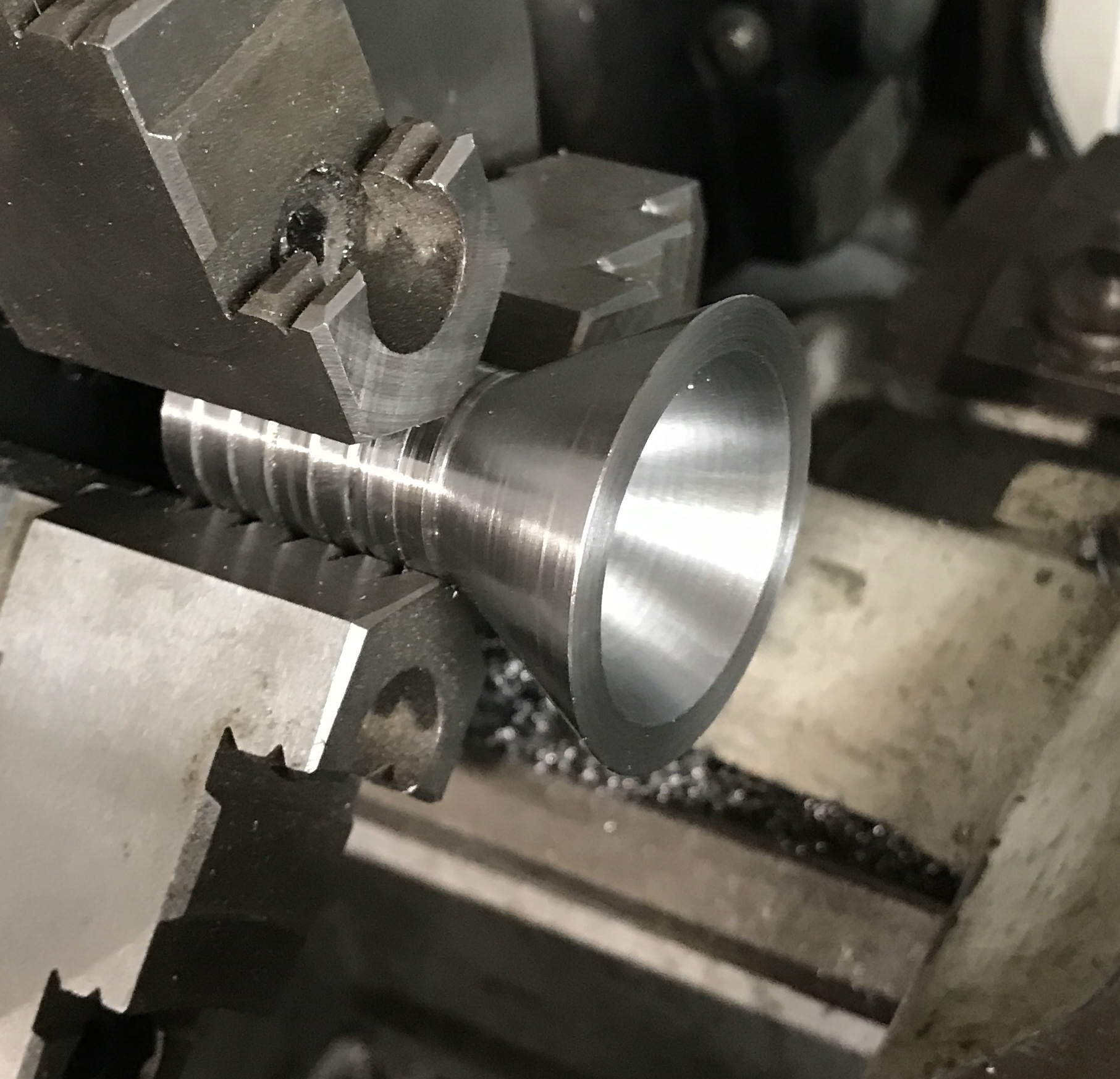
A 3 1/2" length of 2" diameter steel was held in the three jaw chuck on the South Bend lathe. The steel was faced and the carriage stop was set to 1 5/16". The cylinder was reduced to 0.813". The compound was set to 30°. After checking clearances the cone was formed. The cut surfaces were sanded to 320 grit. The first photo below shows cone cutting and the second shows the completed and sanded cone.
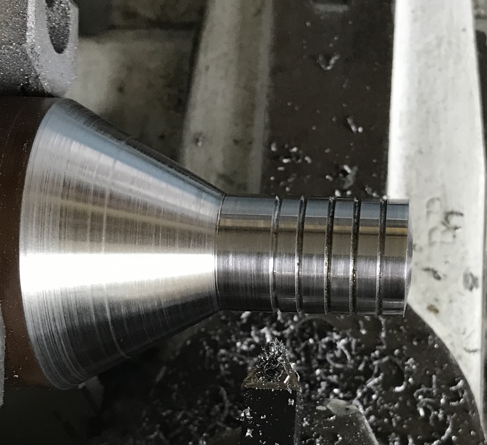
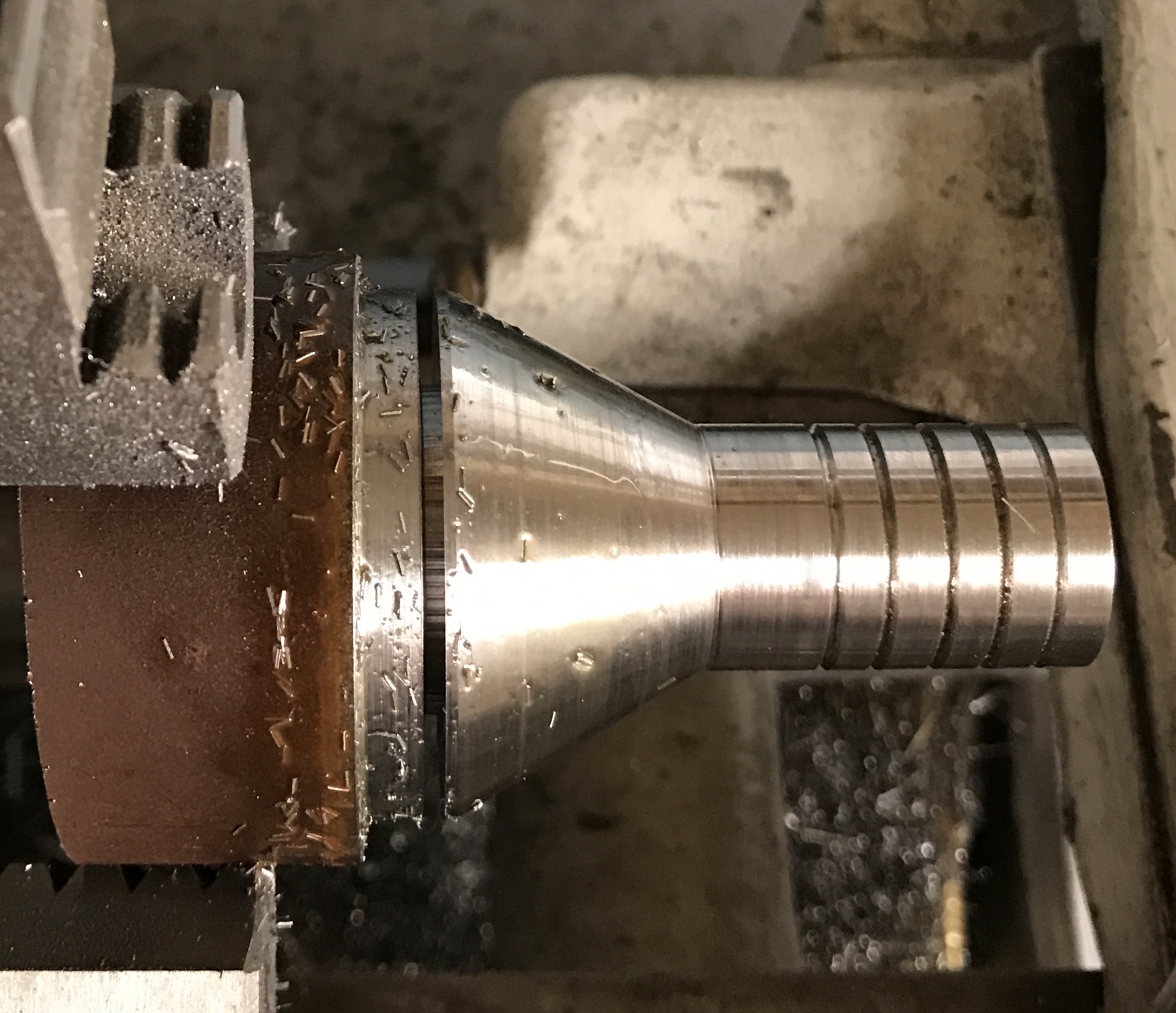
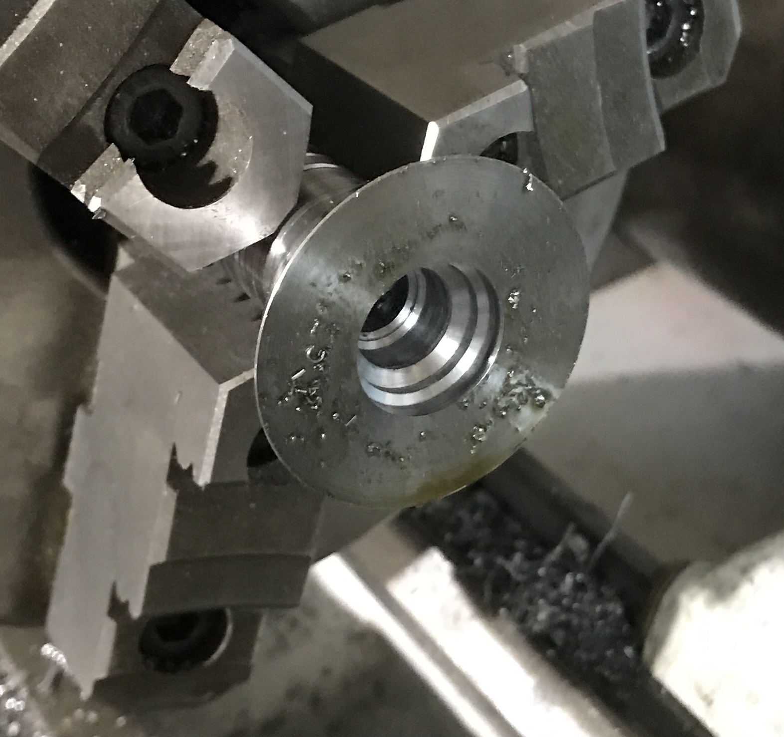
The next steps are two decorative features: beveling the end and adding some grooves. The compound was set at 10°. A bevel was cut across the end of the part. I did not take it to center as the hole was to be drilled later. A 60° bit was set in the tool post and the compound was returned to 30°. The tool bit was aligned with the cross slide. Five 0.03" deep grooves were cut at 7/32 from the end, and then at 3/16" spacings. The photo below shows the result.
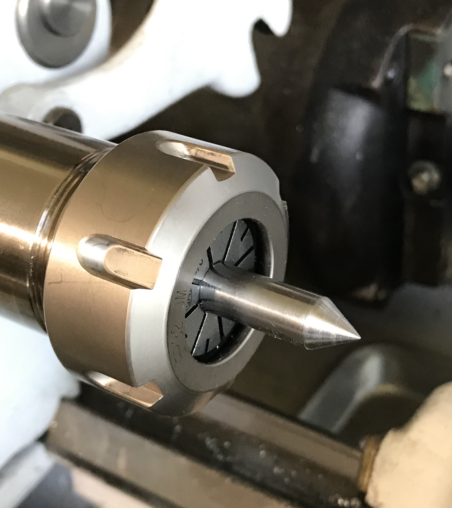
Parting off was the next step. The small parting tool was used after moving the piece a little farther out of the jaws. The parting tool went about halfway. The remainder was cut with tha hacksaw. The part was turned in the three jaw chuck. I do not have a collet large enough to hold it. My ER-32 collets stop at 3/4". Looked into buying a few more, but they stop 1/32" higher.
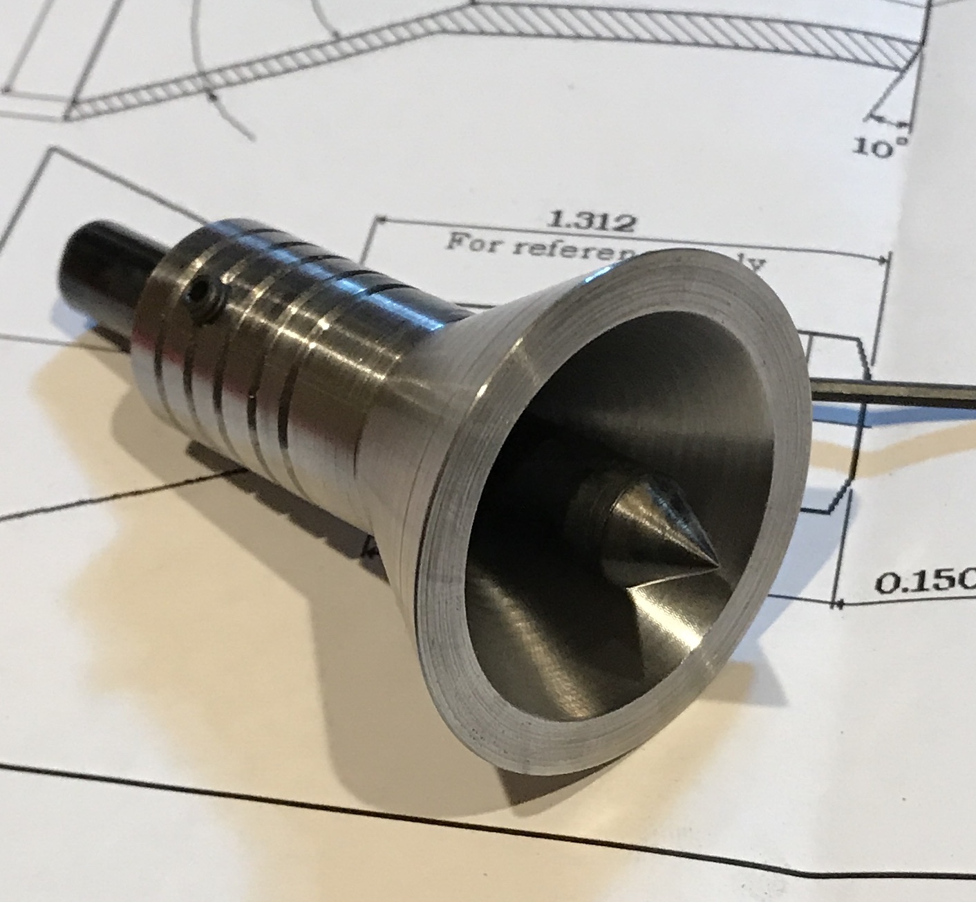
The end was faced to length. The final outside diameter is 1.70", about 1/32" smaller than the plan. A through hole was drilled first with a large center drill and then with a 5/16" drill. In steps of 1/8" the hole was opened up to 3/4", but less deep with each drill. None of the drills beyond 5/16" went past the cone. The boring bar was aligned with the outside of the cone by adjusting the compound. The cone was then opened up with the inside taper in increments of 0.010". There was very little chatter. The inside and outside edges of the cone were lightly chamfered. The final thickness of the cone is 0.20", right on target.
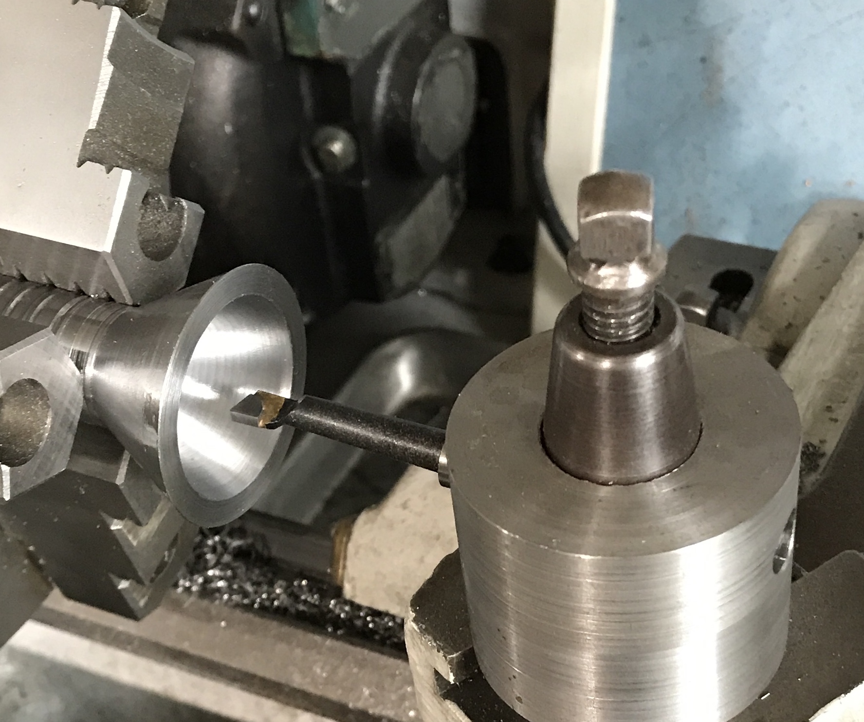
I do not have a boring bar that is long enough to go through the cone and the shaft. I decided to try boring only the first 5/8" of the 1 5/16" hole. I hoped that this would be sufficient to guide the final drilling and reaming. If not the hole will not be concentric with the cone, rendering the tool useless. The boring bar is 5/16" and fit a little tightly in the 5/16" hole. The hole was first opened with a 21/64" drill. The hole was then bored until a 23/64" drill was a tight fit. The 23/64" drill was used to drill all the way through and the 3/8" reamer finished the job.
The hole in the small end was chamfered. The tool was tried out at this stage with a 3/8" punch. A suitable piece of steel was found that happened to have bluing on the end. Two lines were scratched in the end crossing in the middle with a center finder. the bell center was placed over the end after removing a few burrs on the edge. The punch was inserted and tapped with a hammer. The photo shows the result. The punched hole looks slightly off center. There are a few caveats, however. The end of the stock seem perpendicular to the shaft, but I did not face it. It is also difficult to make sure the bell center punch is aligned with the shaft. I will need to do a few more experiments before knowing for certain that the center hole and the taper are not concentric.
Did some checking on the inverter from Automation Direct. The cable they sell to connect the keypad to the inverter does not have the same number of pins as the RS-232 cables on Amazon. So I had to pay three times the price plus shipping for a 1 meter cable! I will need to find some way to affix the keypad to the top of the cabinet.
I also am continuing to better understand the settings I programmed into the inverter. The limiting top speed is the max speed of the motor, which I have not been able to find. Right now it is set to the speed listed on the motor information plate, 1425. This is probably low. I did check the speed of the motor relative to the reading on the inverter. The inverter reading is accurate to within < 1%.
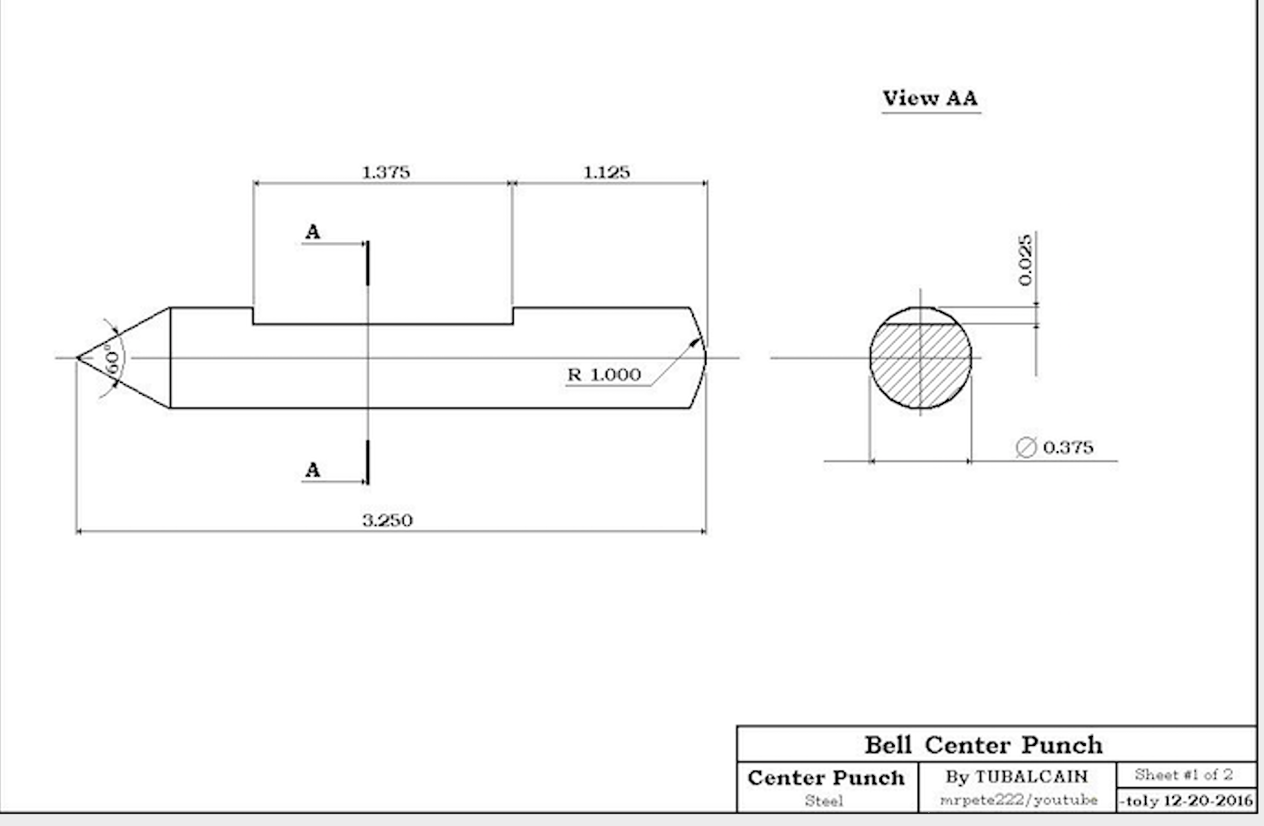
A 3 1/4" length of 3/8" drill rod was cut off. It was held in a collet on the South Bend lathe. The rod was faced on one end and the end was rounded slightly with a file. It was turned around in the collet and the compound was set to 30°. The end was cut until it was close to a point. It was then filed and sanded. Sanding on paper by hand was the best way to get to a sharp point. The point was sanded up to 400 grit. The part was strap clamped on vee blocks. It was marked 1 1/8" from the end and again 1 3/8" farther along. A 5/16" end mill was used to cut the flat 0.025" deep between the marks.
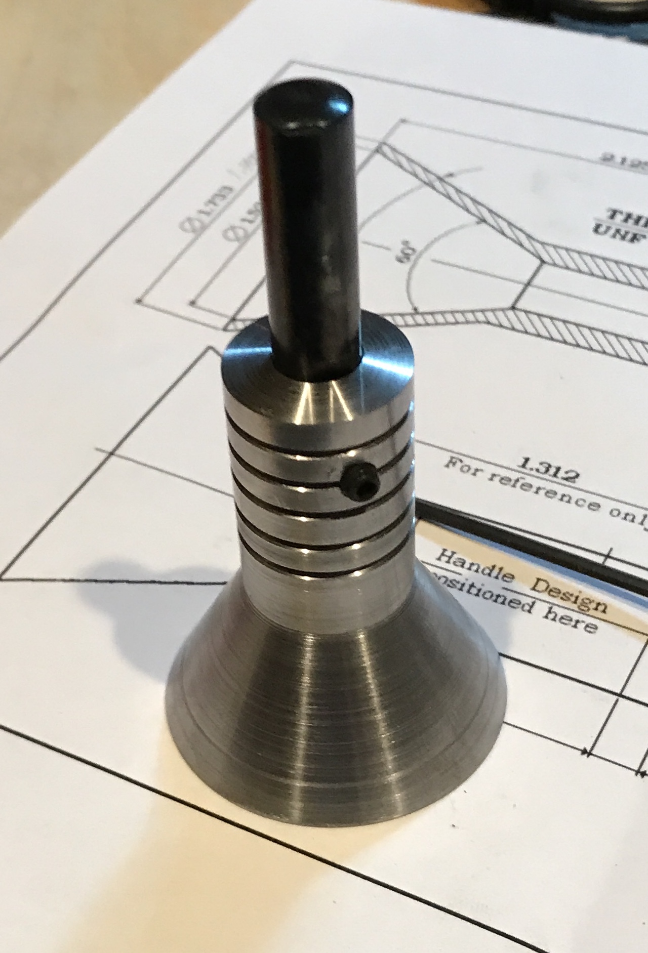
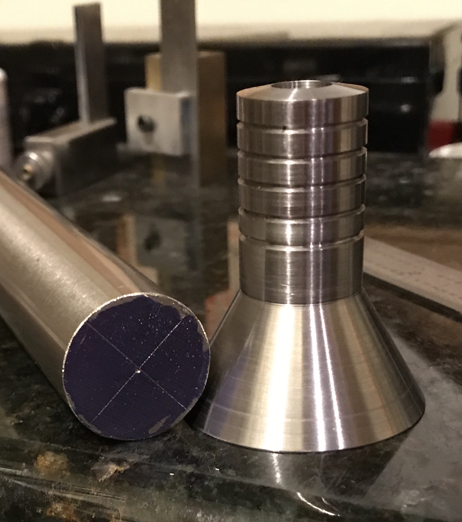
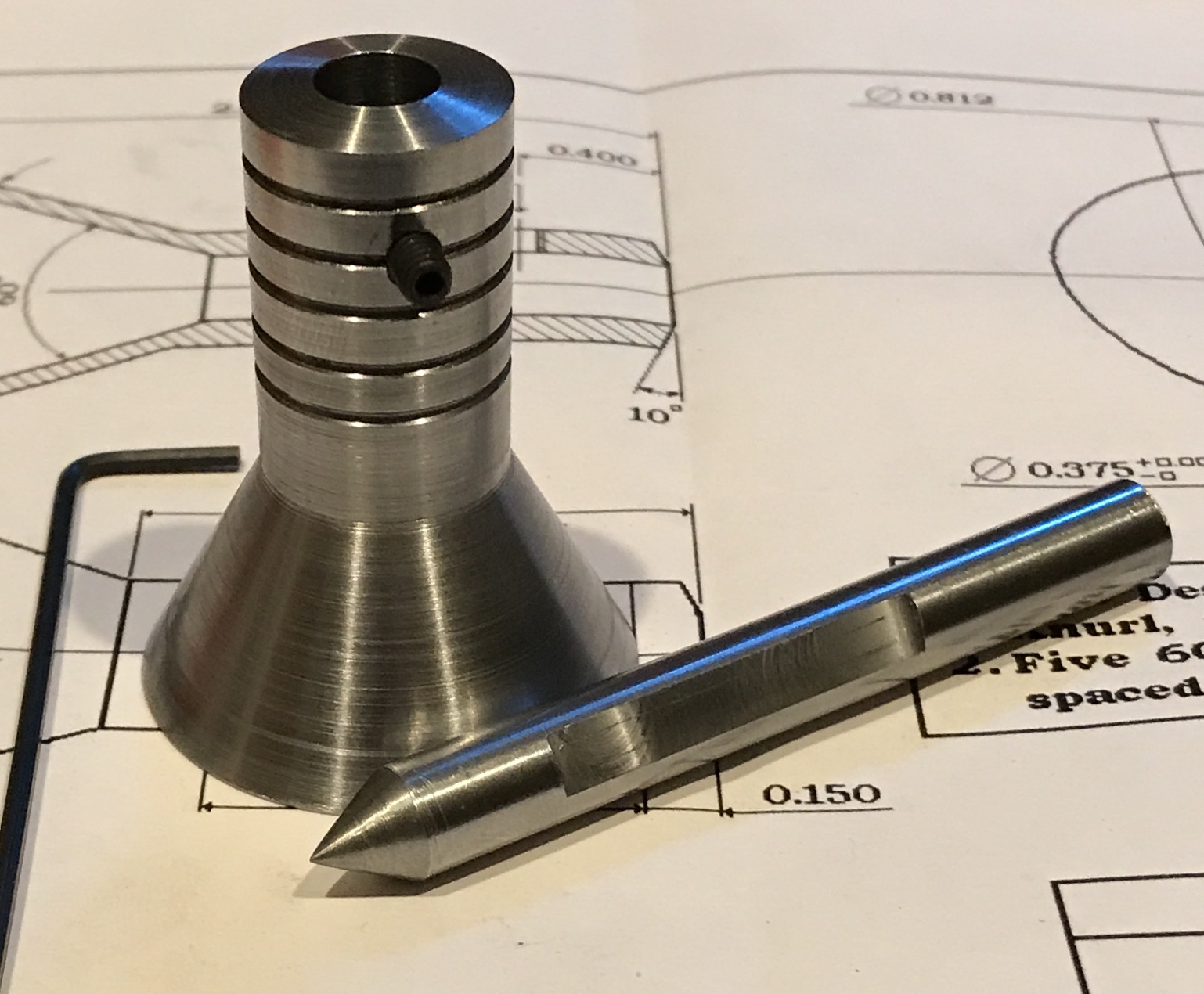
The bell was held in the vise. The center was located. The spindle was aligned with the second vee groove. A hole was center drilled, drilled through with a #29 drill, and tapped 8-32. The center hole was reamed to get rid of the burr. The first photo below shows the point cut on the lathe. The second shows the almost completed parts.
The punch was hardened. It was heated to cherry red on two pavers with the propane torch. It was quenched in motor oil in an old coffee can. After cooling and removing the excess oil the punch was reheated to blue and again quenched. Two shots of the completed bell center punch are shown below.